Ir Arriba Ir abajo


Bienvenidos en chino
Mobbing-acoso laboral-IRG
Mostrando entradas con la etiqueta Chemical Engineering. Mostrar todas las entradas

Electrodeposition of Si, Ti, and W A New Concept of Molten Salt Systems

Abstracts


This Account describes the results of the electrodeposition of film-like Si, Ti, and W by utilizing molten salts selected based on a new concept. The proposed molten salt systems, KF–KCl and CsF–CsCl, have high fluoride ion concentrations, relatively low operating temperatures, and high solubility in water.

First, KF–KCl molten salt was used for the electrodeposition of crystalline Si films to establish a new fabrication method for Si solar cell substrates. The electrodeposition of Si films from the molten salt at 923 and 1023 K was successfully achieved using K2SiF6 or SiCl4 as the Si ion source. The crystal grain size of Si was larger at higher temperatures, indicating that higher temperatures are advantageous for the application of Si solar cell substrates. The resulting Si films underwent photoelectrochemical reactions. Second, the electrodeposition of Ti films using the KF–KCl molten salt was investigated to easily impart the properties of Ti, such as high corrosion resistance and biocompatibility, to various substrates. Ti films with a smooth surface were obtained from the molten salt containing Ti(III) ions at 923 K. Electrochemical tests in artificial seawater revealed that the electrodeposited Ti films had no voids and cracks and that the obtained Ti-coated Ni plate had a high corrosion resistance against seawater. Finally, the molten salts were used for the electrodeposition of W films, which are expected to be used as diverter materials for nuclear fusion. Although the electrodeposition of W films was successful in the KF–KCl–WO3 molten salt at 923 K, the surface of the films was rough. Therefore, we used the CsF–CsCl–WO3 molten salt, which can be employed at lower temperatures than KF–KCl–WO3. We then successfully electrodeposited W films with a mirror-like surface at 773 K. Such a mirror-like metal film deposition has not been reported before using high-temperature molten salts. Further, the temperature dependence of the crystal phase of W was revealed by the electrodeposition of W films at 773–923 K. β-W was obtained at 773 and 823 K, α-W was obtained at 923 K, and a mixed phase of α- and β-W was obtained at 873 K. In addition, single-phase β-W films with a thickness of approximately 30 μm were electrodeposited, which has not been reported before.

The results show that our proposed molten salt systems are advantageous for electroplating Si, Ti, and W. Our approach is also expected to be applicable for the electrodeposition of other metals such as Zr, Nb, Mo, Hf, and Ta.

A New Concept of Molten Salt Systems for the Electrodeposition of Si, Ti, and W
Yutaro Norikawa and Toshiyuki Nohira
Accounts of Chemical Research Article ASAP
DOI: 10.1021/acs.accounts.2c00855

Source: ACS Publications

Fractional Distillation Introduction

Click on image

Fuente: ChemSurvival

Evaporative Crystallization with Recycle Rachael L. Baumann, Janet deGrazia, and John L. Falconer


Fuente: Demonstrations.Wolfram.com

Flash Vaporization of a Heptane-Octane Mixture Wolfram Demostrations Project


Fuente: Demonstrations.Wolfram.com

Ingeniería Química Motor de Desarrollo

Clic en la imagen

El objetivo fundamental del video es presentar a la sociedad cuál es el quehacer de la Ingeniería Química y su diferencia con otras profesiones, principalmente con la Química.

Fuente: CP IQ

Hysys Tutorial 5 examples
James M. Lee

Click on image

HYSYS is an interactive process engineering and simulation program. It is powerful program that you can use to solve all kinds of process related problems. However, since you have to provide various conditions and choices in order to solve a problem, you cannot use it effectively unless you have good knowledge about the process and the solution procedures. The objective of this class is to introduce you to the program so that you can use it as you take core chemical engineering courses in the future.

You can find all kinds of documentation (tutorials, manuals, examples, etc) from the following web site:

http://www.hyprotech.com/hysys/support/index.html - HYSYS%20Documentation

You can find numerous other resources by searching the web. You search results will include many course web sites of other chemical engineering departments. Let’s start with simple examples to find out how HYSYS works.

Hydrogen Orbitals Wolfram Demostrations


Fuente: Demonstrations.Wolfram.com

Torre de Destilación Petróleo

Torre de Destilación de Petróleo
Fuente:
"El Pozo Ilustrado".
Berenice Gómez T. y María Claudia González T./Caligraphy C.A.

Distillation of an Ethanol-Water Mixture Housam Binous


Fuente: Demonstrations.Wolfram.com

Azeotropes of Binary Mixtures Containing Ethanol Housam Binous and Brian G. Higgins


Fuente: Wolfram Demostrations Project

A new roasting process slated for commercialization Edited by Gerald Ondrey

Outotec Oyj (Espoo, Finland; www.outotec.com) has introduced a new partial roasting process to purify copper and gold concentrates that are contaminated with arsenic, antimony and carbon. The process is a pretreatment stage for Cu- and Au-extraction plants, and enables the extraction of metals from ores that had previously been unattractive because the impurities create a “huge problem” of handling dust laden with As and other intermediate products formed in conventional Cu or Au smelters, says Lars Hedstrom, head of Outotec’s Roasting Competence Center in Skelleftea, Sweden.


In the new process (flowsheet), ore concentrate is fed to the top of a fluidized-bed roaster. Preheated air is added through a large numbers of tuyeres at the furnace bottom. The air acts as fluidization media and supplies oxygen to the roasting reactions. Heat is generated by exothermic combustion reactions whereby iron sulfide in the concentrate is oxidized to magnetite and a SO2-rich process gas.

Impurities, such as As and Sb, are vaporized at the high reaction temperature, and thus removed from the solid calcine that contains the valuable metals (normally Cu, Au and Ag). Most of the calcine is pneumatically transported out from the roaster and separated from process gas in cyclones; the more-coarse fraction of calcine leaves the roaster through the bed outlet. The calcine is cooled to stop further reactions between calcine and air. This cooled calcine is now a raw material to conventional copper smelters. It contains enough sulfur to be mixed with conventional copper concentrates to make a suitable feed for oxygen based processes.

Meanwhile, the process gas contains combustible sulfur compounds, such as arsenic sulfide and elemental sulfur; these compounds are oxidized in the post-combustion chamber using preheated air. The process gas, now only containing oxide compounds, is cooled in a cooling tower and then cleaned of its dust content in a hot electrostatic precipitator (ESP). Arsenic oxide passes through the ESP and is wash solution when the gas is quenched in a washing tower. The SO2-rich process gas is further cleaned and converted into sulfuric acid. Arsenic is converted into stable compounds by separate conversion processes, which are also supplied by Outotec.

The process was first demonstrated about 30 years ago in a 45 ton/h plant, which is still operated by Boliden in Sweden. Outotec is now operating a 25 kg/h pilot plant in Frankfurt, Germany.

The company is also currently building the world’s largest As-removing roasting furnace at Codelco Mina Minstra Hales mine near Calama, northern Chile. The new plant will treat up to 550,000 metric tons (m.t.) of Cu concentrate per year and it will produce approximately 250,000 m.t./yr of H2SO4. More than 90% of the As contained in the concentrate will be removed, says the company.

Fuente: Chemical Engineering - www.che.com - March 2012

Avoiding Pressure Relief Problems Chemical Engineering©
Department Editor: Scott Jenkins

Pressure Relief Problems

Pressure relief valves and rupture disks are critical safety devices for protecting personnel and processing equipment from overpressurization situations. Presented here are several engineering practices that can help to identify and address common problems with the pressure relief systems of chemical process industries (CPI) facilities.

Common causes of overpressurization
Overpressure situations can have a variety of causes. Here are some common situations that may cause increased pressure in processing facilities. Each potential cause is followed by one or more factors that contribute to the overpressure.
  • External fire: Potential vapors from the fire must be relieved with a safety valve on the vessel
  • Blocked outlets: Blocked outlets can be caused by control valve failure, inadvertent valve operation and others
  • Utility failure: General or partial power failure, loss of instrument air, cooling water, steam, fuel gas or fuel oil
  • Loss of cooling duty: Loss of quench steam, air-cooled exchanger failure, loss of cold feed or loss of reflux
  • Thermal expansion: External heat can cause liquid volume to rise in fluids that are blocked in a vessel or pipeline
  • Abnormal heat input: Increased supply of fuel gas, or faster heat transfer after exchanger revamp, and others
  • Abnormal vapor input: Failure of upstream control valve to fully open, or inadvertent valve opening
  • Loss of absorbent flow: Interruption of absorbent flow when gas removal by absorbent is more than 25% of total inputvapor flow
  • Entrance of volatile materials: Ingress of volatile liquid into hot oil in a process upset
  • Accumulating noncondensibles: Blocking of noncondensible vent
  • Valve malfunction: Human error or checkvalve malfunction, resulting in backflow, control valve failure
  • Process control failure: Failure of distributed control systems (DCS) or programmable logic controller (PLC)
Valves
To avoid problems with pressure relief systems, plant managers should consider these
practical guidelines.

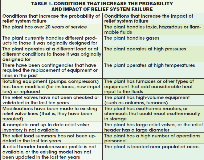
Assess risk. Many factors can increase the risk and impact of pressure-relief-system failure. If several of the conditions in Table 1 apply, plant managers should consider planning a detailed study of the pressure relief systems, such as a quantitative risk analysis (QRA) or a relief-system validation study.

Maintain up-to-date relief-valve data. Plant managers should maintain accurate and
up-to-date relief-valve data, including relief valve inventory, relief-valve load summary and relief-header backpressure profile. The inventory is a list of basic information that applies to each valve, such as process unit, location, discharge location, connection sizes, orifice size, manufacturer, model, installation date, and date of last inspection.

The loads summary contains all the overpressure scenarios and relief loads for each device at the plant. The backpressure profile of the pressure-relief network is valuable when evaluating the critical contingencies of the systems, as it can be used to identify relief valves operating above their backpressure limits.

Relief-system study. A relief-system validation study comprises three phases:
  1. survey and information gathering
  2. modeling of the existing relief system and
  3. relief system troubleshooting
Modeling. Results from accurate modeling can identify the need for replacement of a relief valve. However, developing an accurate model for every relief valve in a plant is costly and impractical. A compromise that minimizes time and effort while targeting potential problem areas is to verify each system starting from a simple model with conservative assumptions, and to develop more accurate models only for those items that do not comply with the required parameters under the original assumptions. See Ref. 1 for an example.

Rupture Disks
Rupture disks are often installed as the last line of defense against overpressurization.

When handled and installed properly, rupture disks are a safe and economical way to protect personnel and process equipment.

To help avoid problems with rupture disks, consider the following guidelines:

Evaluate pressure measurement. Since most rupture disks react to overpressure within milliseconds, it is important to sample and measure the pressure near the rupture disk, and at time intervals that are narrow enough to catch rapid pressure spikes.

Evaluate fatigue and corrosion of disks. Process engineers should pay attention to the effects of corrosion and fatigue on the performance of rupture disks. In some cases, rupture disks are operating at up to 95% of their rated burst pressure.

And rupture disks can have thicknesses of 0.001 in. If a change in material thickness occurs because of corrosion or changes in operating pressure occur, failures can occur.

Check installation. As precision devices, rupture disks have tight burst tolerances. Because of this, it is critical that the rupture disk be installed correctly, with attention to torque, position and possible inadvertent damage to seating surfaces. See Ref. 2 for features that aid installation.

Check process temperature. The strength of the materials used to manufacture rupture disks is always dependent upon the temperature. It is important that rupturedisk burst pressures are specified for the temperature at which they will operate. It is important to keep in mind that it is possible that the specified burst pressure may not be the same as the temperature inside the vessel, especially if the vessel is insulated.

References
1. Giardinella, S. Aging Relief Systems — Are they working properly? Chem. Eng., July 2010, pp. 38–43.
2. Wilson, A.T. Troubleshooting Field Failures of Rupture Disks. Chem Eng. December 2006, pp. 34–36.
3. Wong, W., Protect Plants Against Overpressure. Chem Eng., June 2001, pp. 66–73.

Intercambio Iónico experiment on ion exchange

Click on image

Fuente: Robertburkottawa

Supercritical Water Process
converts Biomass to Sugars Chemical Engineering

Sugar is a critical feedstock for many emerging bio-based-chemical and biofuel processes, but harvesting sugar from lowvalue, nonfood biomass cost-effectively and at large scale remains a challenge. Renmatix Inc. (King of Prussia, Pa.; www.renmatix.com) has developed a process that uses water above its critical temperature and pressure to hydrolyze a range of biomass materials to make C5 and C6 sugars. Unveiled at an event last month, the Renmatix process, known as Plantrose, offers what may be the lowest-cost approach to supplying sugar for the growing bio-chemical and renewablefuel markets.

The company currently converts three dry-tons per day of waste hardwood chips into sugar at a demonstration facility in Kennesaw, Ga. Renmatix CEO Mike Hamilton says the company will announce next year the location of a planned commercialscale facility that will be capable of producing 100,000 ton/yr of sugar. The first plant may be co-located with a bio-based chemicals maker that can use the sugar from Renmatix’s process.

The Plantrose process is built around a supercritical hydrolysis platform, which capitalizes on the ability of supercritical water (SCW) to depolymerize cellulose, where water below the critical point cannot. Another unique aspect of the process is its two-step method that first separates the easier-tobreakdown hemicellulose before subjecting the tougher cellulose to SCW conditions that would destroy the C5 sugar. Plantrose begins with a slurry of waste woodchips that enters a fractionation reactor, where hemicellulose is solubilized into a C5 sugar stream. The remaining solids (cellulose and lignin) are then subjected to precisely controlled conditions that bring water above its critical point to generate glucose. The lignin is separated and collected as a solid.

The speed of the SCW hydrolysis (seconds) contributes to lower capital expense, says Hamilton, adding that the Plantrose process requires no significant consumable materials and utilizes heat from burning the solid lignin, so production costs are low.

Ref: CHEMICAL ENGINEERING - WWW.CHE.COM - NOVEMBER 2011

Documentos Técnicos de un Proyecto Normas, Ingeniería Básica, de Detalle, Diagramas

Documentos Técnicos de un Proyecto

Carbon storage and
electricity generation project gets DoE funding

DoE

A project aimed at using geothermal heat to power an electricity-producing turbine with supercritical carbon dioxide has received a $5 million grant from the U.S. Dept. of Energy (DoE; Washington, D.C.; www.energy.gov). The project also incorporates an element of CO2 sequestration in sedimentary rock, whereby a portion of th CO2 injected into the hot sedimentary layer remains there, so that the process requires a constant stream of CO2.

The three-year project, led by researchers at Lawrence Berkeley National Laboratory (Berkeley, Calif; www.lbl.gov), represents the first attempt to convert geothermally heated CO2 into useful electricity.

"The project is focused on validating the concept of using CO2 as a working fluid in the subsurface for geothermal energy production," says Berkeley Laboratory researcher Barry Freifeld.

The process would begin by injecting CO2 into a wellbore at a supercritical state (pressure above 70 bars and temperature greater than 31ºC ) into a layer of 125ºC sedimentary rock that lies over 3 km beneath the earth's surface. Under these conditions, CO2 becomes more pressurized and further heated in the underground rock. The higher-pressure, higher-temperature CO2 is extracted through a separate but nearby producer well.

It is expanded through a heat-engine turbine, where is higher entalphy is converted to shaft work. The turbine generates electricity, and the CO2 is cycled through the loop again.

The geothermal-heat system will be designed so that a portion of the CO2 remains stored in the rock, and a continuous supply fo new CO2 will be supplied to the loop.

The turbines, to be designed and built by Echogen Power Systems (Akron, Ohio; www.echogen.com), will be based on technology already developed by the company (a supercritical CO2) based power-generation system for low temperature waste heat recovery that has a turbine similar to that required by the geothermal project.

Pilot testing is planned for the third years of the project an the Cranfield site in Mississipi, where a DoE injector well an two heavily instrumented monitor wells for carbon sequestration research already exist.

Ref: Chemical Engineering Magazine - www.che.com - September 2011, pag. 14.

Heat Transfer System Cleaning Department Editor: Scott Jenkins
Chemical Engineering©

A well designed and operated heat-transfer-fluid system is a key feature of a safe, reliable and cost-effective heating design. However, problems can arise if the heat-transfer fluid becomes heavily degraded or the system is allowed to accumulate solids and other process contaminants.

These problems include the following:
  • Reduced heat-transfer rates
  • Diminished fuel efficiency
  • Flow blockage in small-dia. or low-velocity areas
  • Extended startup times at low temperatures
  • Fouling of heat-transfer surfaces
  • Overheating, damage or failure of heater tubes
Avoiding heat-transfer fluid degradation and contamination often requires the use of the following filtration, flushing and cleaning techniques.

Filtration
In many cases, filtration can effectively remove solids that, if left unchecked, may result in the need to drain and flush a system. In general, glass-fiberwound
filter cartridges work well for in-system filtration of organic-liquid heat-transfer fluids.

These filters are generally available from numerous manufacturers, are usable at temperatures up to 400°C, typically have adequate solids-holding capacity and are usually economical and disposable.

The filter housing should also be specified for the desired temperature and pressure.

The filter should be installed where there is a 20–40-psi pressure drop, and should have a maximum throughput of 1% of the system flowrate. For initial startup, a 100-μm-nominal particle removal rating is acceptable, and can be gradually reduced to a 10-μm-rated filter element for ongoing use. For heat-transfer fluids containing high concentrations of solids, bag filters or other high-surface-area designs may be preferred.

When intensive system cleaning is necessary, it is recommended to incorporate sound environmental, health and safety principles into the job plan to protect against exposure to hot fluid and vapors.

System drain
Adjust the fluid temperature to 93°C and shut down the heater. Continue operating the circulating pumps as long as possible during pump-out to keep loose solids and sludge in suspension.

Drain the system through all low-point drains. If gravity draining is not sufficient or possible, compressed nitrogen can be used to effectively blow additional fluid from the system. Remove as much degraded heat-transfer fluid as possible to maximize the following cleaning techniques. Caution must be exercised to avoid contact with hot fluid and piping. Once the fluid has been drained from the system it should be stored, handled and disposed of according to the product MSDS (material safety data sheet) and your environmental, safety and health professionals’ guidance. The system may then be cleaned using one or more of the techniques in Table 1.

System ushing
If a strainer is not already present in the system return line that runs to the main circulating pumps, consider the addition of a fine-mesh strainer to protect the circulation pumps from solids that may be dislodged during cleaning.

When choosing a flushing fluid, ensure that it is compatible with the system components and the new replacement fluid. This can usually be determined by contacting the fluid manufacturer. In addition, avoid flush fluids that contain chlorine, as this may cause corrosion issues if a portion is left in the system.

Fill the system from the low points with the flushing fluid, including the expansion tank, to a normal operating level. Start circulating the entire system at ambient conditions to begin dissolving the organic solids and residual heat-transfer fluid.

Periodically check the return line strainer for plugging and buildup of solids that may have been released during system cleaning. In accordance with the manufacturer’s recommendations, increase the fluid temperature to maximize cleaning potential and continue circulating for the directed time period. Cool the flushing fluid, then drain it from the system through low points, ensuring that as much fluid is removed as possible, then dispose of it properly.

Chemical cleaning
In some situations, alternative cleaning methods are required, such as cleaning of a vapor-phase heat-transfer system. In these situations, chemical cleaning may be used as an alternative. In general, chemically cleaning a heat transfer system requires extra steps, higher cost, additional time and producessignificantly more waste. A general outline of a chemical cleaning procedure may include the following:
• Drain heat-transfer fluid from system
• Solvent flush circulation
• Drain solvent flush
• Acidic solution circulation
• Caustic and detergent solution circulation
• Flush with water
• Dry thoroughly

Mechanical cleaning
In some cases, such as when the system has been severely fouled by hard coke deposits or the lines are completely blocked, the above methods are inadequate for cleaning the system. In these cases, mechanical cleaning is most likely required.

Mechanical cleaning methods can include highpressure water jetting, wire brushing, mechanical scraping and sand or bead blasting.

After cleaning
Once the system has been drained completely, it should be inspected for solids that may have fallen out of suspension, especially in low-velocity areas.

Ensure that a side-stream filter is operational and properly maintained. If a side-stream filter is not present in the system, consider installing one to aid in solids removal during normal operation.

Refill the system with fresh heat-transfer fluid and start up using normal procedures. Residual moisture may be present from the drain, cleaning and start up procedures. Care should be taken to vent any moisture from the system by allowing
flow through the expansion tank where the moisture can flash and then vent. It is also suggested to employ inert gas blanketing of the expansion-tank vapor space to prevent moisture and air contamination of the fluid. This is usually put in place
after moisture has been vented and the system is brought up to operating temperature.

References and further reading
1. Beain, A., Heidari, J., Gamble, C.E., Properly Clean Out Your Organic Heat-Transfer Fluid System, Chem. Eng. Prog., May 2001, pp. 74–77.
2. Gamble, C.E., Cleaning Organic Heat Transfer Systems, Process Heating, Oct. 2002, pp. 39–41.
3. Solutia Inc., “Therminol Information Bulletin no. 1: Cleaning Organic Heat Transfer Fluid Systems,” Pub. no. 7239011B, Solutia Inc., 2008.
4. Solutia Inc., “Therminol Information Bulletin no. 3: Heat Transfer Fluid Filtration: How and Why,” Pub. no. 7239123B, Solutia Inc., 2004.

Editor’s note: Content for this edition of “Facts at Your Fingertips” was contributed by Solutia Inc.

New Membrane Bioreactor It cuts energy costs and boosts throughput
Chemical Engineering©

GE Power & Water (Trevose, Penn.; ge.com) has introduced an improved membrane bioreactor (mbr) technology whose productivity is said to be 15% higher than that of its predecessor for wastewater treatment plants. The new system, called LEAPmbr, was derived from innovations to GE’s ZeeWeed 500 mbr.

Glenn Vicevic, senior manager, Engineered Systems, says the system has been tested on a commercial scale at three of its customers’ plants and has demonstrated several improvements in addition to higher productivity. These include a 30% reduction in membrane energy costs, a 50% reduction in membrane aeration equipment and controls, and a 20% smaller footprint.

The system consists of rectangular cassettes of PVDF hollow-fiber membranes, immersed in a bioreactor in which bacteria break down pollutants. A pump draws treated water through the membranes, while solids, bacteria and colloidal material are retained in the tank.

An improved aeration method for cleaning the membranes was the key element in lowering energy costs, says Vicevic. “The conventional wisdom is that there should be a continuous air scour of the membranes,” he says, “but over the last decade, we experimented with bubble-size-diffuser design and frequency of air release. From that we determined that large bubbles delivered intermittently was the most effective.” He adds that the improved productivity was obtained by optimizing the manufacturing techniques, while the smaller footprint was achieved by increasing the surface area of the membrane.

Ingeniería de las Reacciones Químicas Introducción

Gas-Liquid Mixing: Physical Considerations Department Editor: Scott Jenkins
Chemical Engineering©

Gas-liquid reactors in the chemical process industries (CPI) have increasingly been designed to handle larger manufacturing scales. Since gas-liquid reactors can represent substantial capital and operating costs for the user, optimizing mixing and maximizing productivity are critical. The need for efficiency at larger scales places more importance on understanding the physical phenomena of mixing and more of a burden on equipment design.

Physical demands of mixing A number of complex physical phenomena must be considered to achieve optimal function of mixing equipment in cases where gaseous and liquid substances interact. For a gas-liquid reaction to occur, a low-density compressible gas must be dispersed into a much denser liquid with a reasonably long contact time.

Usually, significant turbulence must be induced into the liquid phase to aid mass transfer and reaction.

In addition, rapid movement of the liquid phase is often required at heat-transfer surfaces, which are often removed by some distance from mixing impellers. In some cases, the liquid phase can contain a significant level of solids, which must be kept suspended.

Gas-liquid reactors commonly consist of large pressure vessels with sophisticated internal components for gas feed and exhaust, liquid feed and outlet, heat-transfer and baffling, as well as agitation.

The two major categories of gas-liquid reactions are those with a “pure” feed gas, and those in which the gas contains a significant fraction of inert gases in addition to the reactant. For a gas-liquid reaction to take place, a molecule of gas must dissolve in the liquid phase and then meet a molecule of the reactant. A catalyst material is often present, in which case both reactants must meet on the active site of a catalyst.

The catalyst’s high specific surface area means that the reaction is usually limited by transport of the gas through the boundary layer around the gas bubbles and into the liquid phase (Figure 1).

The specific rate of mass transfer through the boundary layer is governed by the standard mass-transfer equation:
m = kLa (c* – c) (1)

where c is the actual concentration of dissolved gas and c* is the theoretical equilibrium concentration of dissolved gas.

The film mass transfer coefficient (kL) is mainly a function of the physical properties of the reactants, and is less sensitive to mixing conditions. The specific surface area (a) also depends on material properties, but can be significantly increased by changes to process design. These two factors are usually expressed together as a specific mass-transfer capacity (kLa), since it is difficult to measure either one directly.

The term (c* – c) in Equation (1) is sensitive to changes in process design in that influences can be designed to increase the theoretical equilibrium concentration of dissolved gas (c*).

According to Henry’s law, the value of c* is proportional to the partial pressure of the reactive gas. So the use of a reactant gas in a pure form raises process efficiency, but the presence of volatile solvents reduces it. Increasing reaction pressure can boost productivity, but higher pressures also mean higher operating and capital investment costs.

The target for the design engineer is to optimize kLa and operating pressure to achieve the required productivity at the lowest cost.

Gases with inert components
Many industrial gas-liquid processes involve reactant gases diluted with significant amounts of inert gases. This includes all processes using air (21% oxygen in nitrogen) or fluegas (carbon dioxide or sulfur dioxide in nitrogen), in which the feed gases and then discharged.
In cases where gases contain to the reaction stoichiometry is considerations, using air as an example:
  • The mass transfer force (c* – c). about one-fifth
  • 100% consumption of the oxygen from air is not possible, so reactors must operate with stoichiometric excess. Exhaust from industrial oxidation processes, for example, typically contain around 4–15% residual O2
  • O2 partial pressure in the dispersed gas phase changes as the O2 is consumed, and this must be taken into account in reactor design
  • Mass transfer cannot be increased by recirculating gas from the headspace, since the headspace gas concentration is depleted
  • Since large amounts of inert gas are present, a stoichiometric excess of reactant is required; often high gas rates result, and flooding of impellers is possible
  • Practically, the loss in mass transfer capacity generally requires larger reactors, and large reactors require particular attention to maintaining the homogeneity of the mixture
Impellers for high gas rates
Traditionally, for reactors that have high gas rates, combinations of impellers, such as flat-blade disc turbines (FBDTs), pitch-blade turbines (PBTs) and wide-foil impellers are used. More recently, impellers with concaveshapes are increasingly being used (Figure 2).

With these impellers, the gas feed can be dispersed into the liquid phase using a radially pumping primary disperser (PD). One or more secondary dispersers (SD) can also be used on the same shaft, but higher up in the liquid to provide a combination of axial blending of the liquid and redispersion of the gas (Figure 3).

The left diagram shows a compartmentalized flow pattern with FBDTs. The right side shows axially extended vortices with the SD. The two vortices created by the FBDT, one above and one below the impeller, “roll” over one another, while The PD/SD system generates significant material exchange in the axial direction. This reduces the required blend time.

When there are significant quantities of dispersed gas present, traditional impellers rapidly lose power, whereas the concaveblade impellers of the PD/SD type are much less affected.

Reference
1. Himmelsbach, W., Kellar, W. Lovallo, M., Grebe, T. and Houlton, D. Increase Productivity Through Better Gas-Liquid Mixing. Chem. Eng., October 2007, pp. 50–58.